Proving a machine-room slab for new lift motors
A City of London office was replacing its lift motors with new, smaller units. Before the machine-room slab could be signed off to carry them, Corvus mapped its reinforcement with GPR and Ferroscan — and rendered it in 3D over the slab — so the engineer could verify it on evidence, not assumption.
The brief
An office building on London Wall was modernising one of its lifts — the existing motors were coming out and being replaced with new, smaller units. Before that could happen, one question had to be answered: could the machine-room slab carry the new motors?
It sounds like the easy part of a modernisation. It isn’t. The machine room sits at the top of the shaft, the slab underneath the motor bedplate is safety-critical, and on an existing building the original reinforcement drawings are often long gone. The engineer needed to know the slab actually contained reinforcement — and how it was laid out, at what spacing and cover — before signing it off against the new loads. Assuming it was fine, or drilling to find out, were both off the table on a live City office.
On site
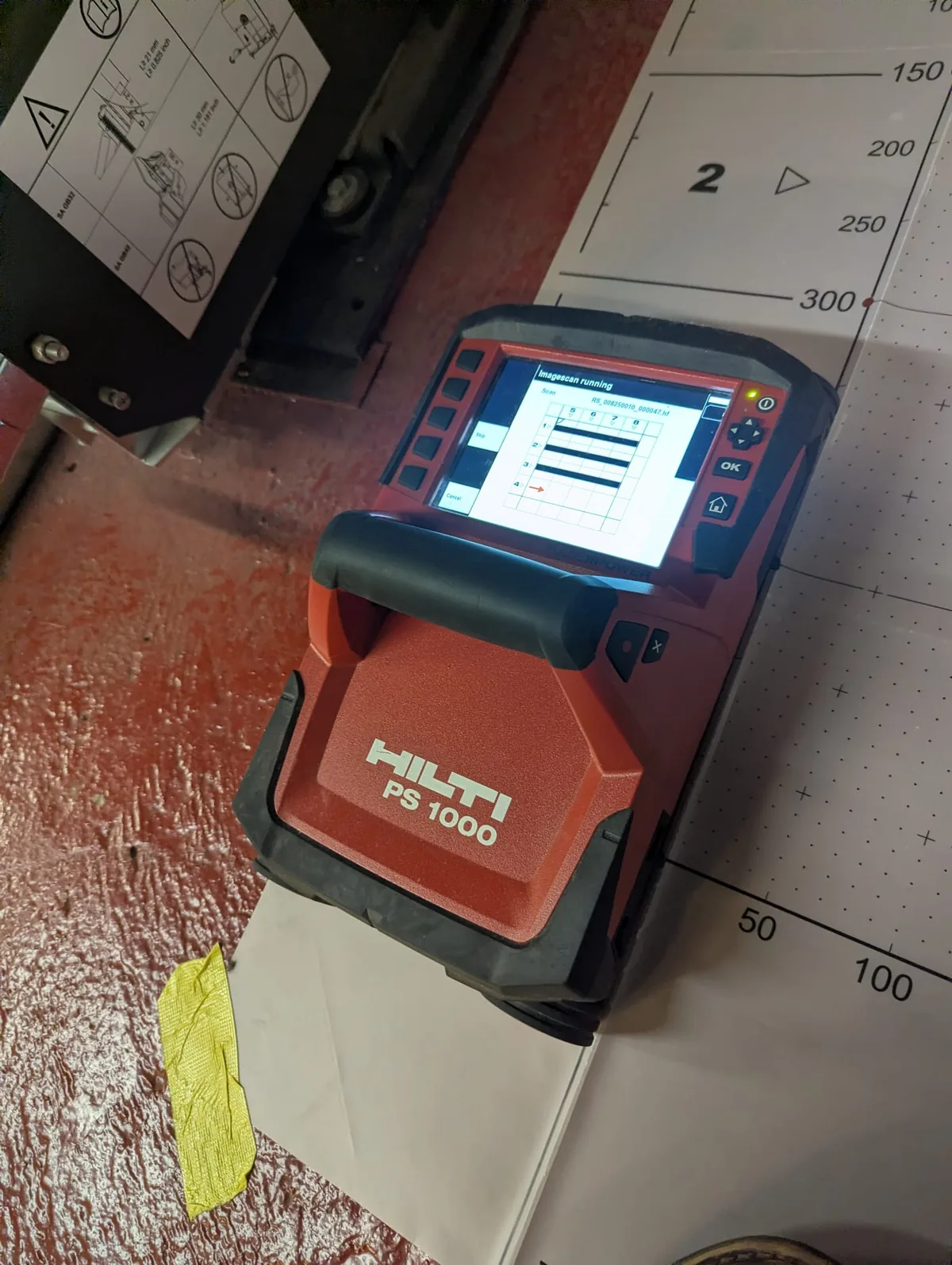
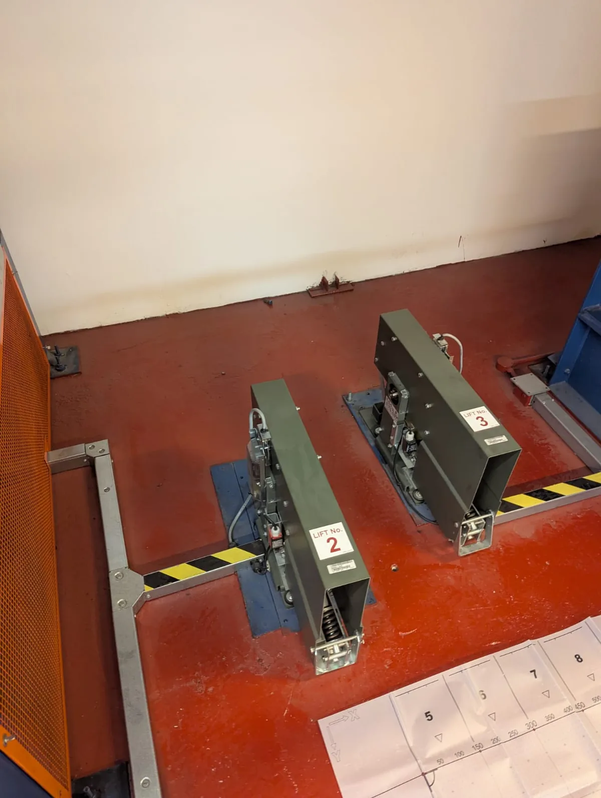
We attended the machine room and scanned the slab with a Hilti PS1000 GPR array, backed up with Ferroscan for cover and near-surface detail. The room was tight and in service — Schindler equipment live either side — so the survey was set out to work around the plant and capture the full run beneath the motor positions.
Each scan line was gridded and marked on the slab, then tied back to the machine-room layout so the data could be read straight against it.
What the scan showed
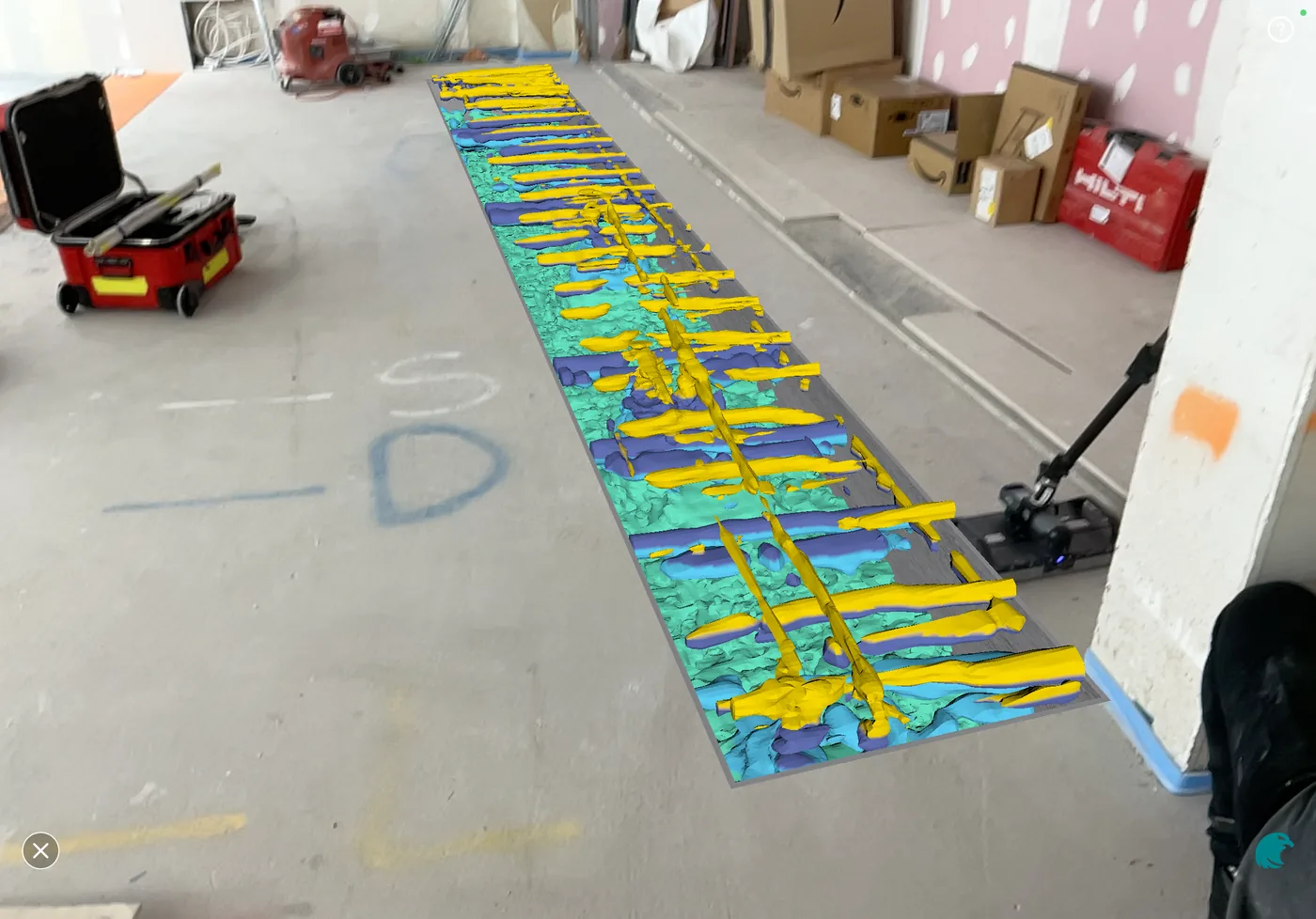
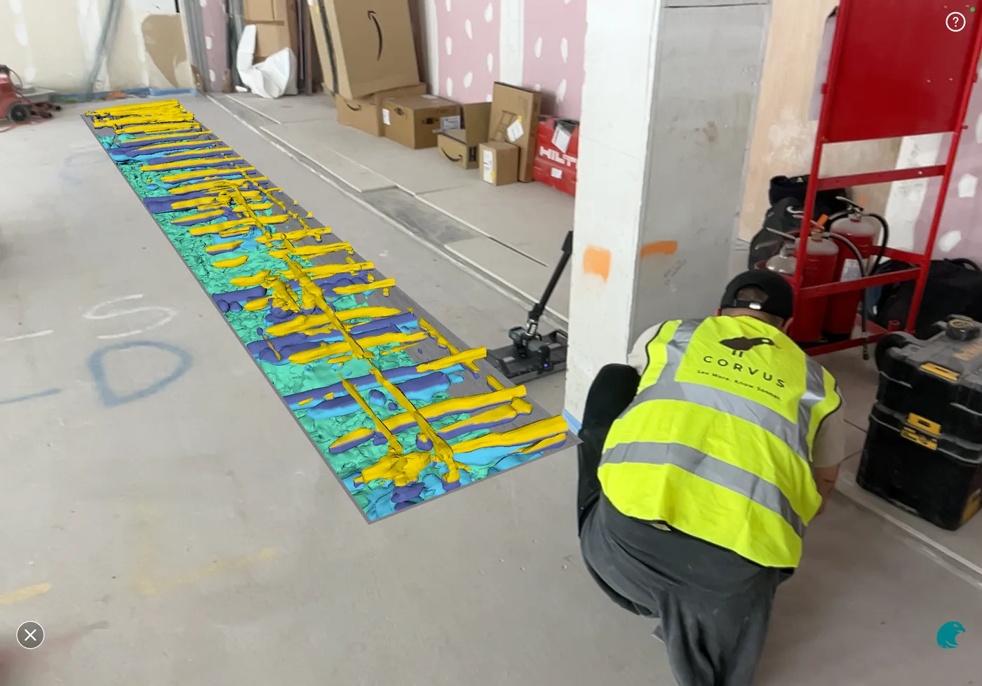
The survey confirmed what the engineer needed first: the slab was reinforced, and the GPR resolved the reinforcement layout and spacing across the motor footprint, with cover measured from the Ferroscan data. Rather than hand it over as flat plots, we rendered the reinforcement as a 3D model registered to the slab — the steel mapped in place, at depth, exactly where it sits under the bedplate.
We were clear about the limits, as we always are: where bar diameter couldn’t be confirmed with confidence from the processed exports, it was flagged for verification from the native scan files rather than stated as fact. A survey that quietly overstates its certainty is worse than useless on a safety-critical fixing.
The deliverable
The engineer received an annotated report, a marked-up machine-room plan showing where each scan sat, and the 3D reinforcement model tied to the slab — so the reinforcement could be located and read against the design of the new motor installation, not guessed at.
The outcome
With the reinforcement layout, spacing and cover in front of them, the engineer verified the machine-room slab against the new motor loads on evidence, before a single machine was lifted in. The modernisation went ahead on a proven slab — no exploratory breakouts into a live City office, no assumptions carried into a safety-critical fixing.